Current status
14 July 2008
The power supply fixed. However, still get bit errors on bit 2, even with the memory supply above 26V (though it does get much better at the higher voltages). Looks like the sense amp μPAC is indeed marginal.
TODO list
- Repair I/O cable outer sheath
- Fabricate missing cable clamp plates for the CPU and Memory/Input-Output tilt-out drawers.
- Reverse-engineer the paper-tape punch I/O device for which I have no schematics. Can I connect this to my FACIT 4070? I suspect that this was designed for a high-speed punch. Definitely a different cable to my H316 punch cable.
- Replace main power cable. Rubber insulation in a poor state.
- Find solution to broken fan power cable connectors on tilt-out drawers.
- Clean cabinet side panels and decide what to do with cable cut-outs in these panels.
- Confirm that the paper-tape reader is working correctly. Previous attempt to boot from paper-tape failed, but this was due to the core memory not being reliable at that time, this is now fixed. Run paper-tape reader VT tests.
- Run ASR VT tests
- Run High-speed arithmetic VT tests.
Memory sense amplifier fixed
June 2008
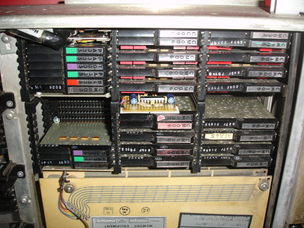
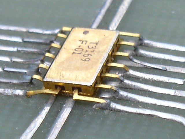
So I've finally found time to get back to the 516 restoration, starting with getting the memory to be 100% reliable again. The problem had been that one of the sense amplifiers had gone wrong. These are on a CM032 μPAC. There are four F-07 chips on each of these packs, providing the amplifiers for two bits. Each bit needs two F-07 chips which contain one sense amplifier since the sense winding for the 8192 bits is divided into two each looping through 4096 cores. Since one of the F-07 chips had gone this meant that half of the memory locations were non functional, but the pattern is apparently random (I'm sure that it isn't really) so that the broken words were scattered throughout the 8k memory map.
Obviously, I'd like to find a replacement F-07 chip, or CM032 μPAC (or indeed CM033 - a one-bit amplifier for the parity bit, where it is used) - if anyone has one that they can part with then please let me know. However, I decided that this wasn't going to be easy to find, and besides I wanted to really understand the core memory by finding another solution.
The approach I've taken is to replace the broken chip with a (slightly) more modern TTL sense amplifier. After a false start with some chips labelled as SN7523N which quite clearly were no such thing (fortunately I didn't connect these to my core stack since I'd have blown the sense winding for sure) I sourced some SN7522N chips. These each provide two amplifiers internally, so I'm only using half of it to replace the functionality of the broken F-07 chip.
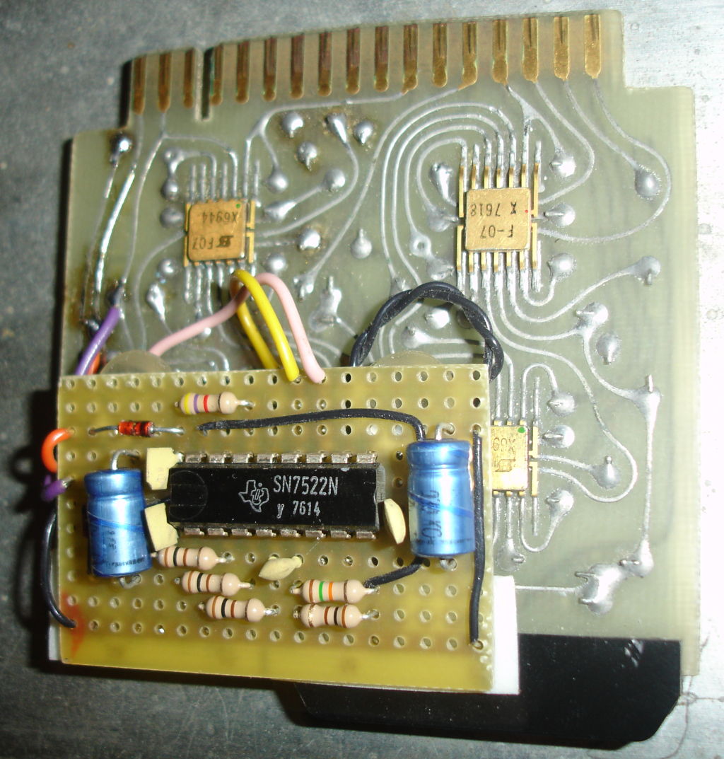
It's not the prettiest fix in the world, but it does work very reliably. I had this on a breadboard for a while and had the devils job trying to get the thing to work. I found that any threshold voltage I set (nominally around 35mV, but I was changing values from around 10mV to around 60mV) would only make some of the memory locations work. If I got one location to reliably sense then others would stubbornly stick at '0'. Change the threshold to fix those and the original location would read-back '1' whether a '0' or a '1' had been written. I eventually figured out that this was due to my lack of care in taking signals onto the breadboard down a ribbon cable. I'd got the strobe signal adjacent to one side of the differential signals from the sense winding. Since the pulse to be sensed can be either positive or negative, depending on the location as the sense winding snakes though the cores, this meant that for some locations the inductive coupling made the pulse larger, whereas for other locations it cancelled it out. Once the penny finally dropped and used a bit of twisted pair for the differential signals the thing worked perfectly.
Power supply fixed
20 September 2006
Had the RP61 power supply in bits. I've no schematics of this supply so it took a while to determine what was going on. The problem was just with the 24V regulated supply, from which there was no voltage at all.
The main 24V regulator board was in pretty poor shape, with evidence that the series power transistor had been getting very hot. (Evidence as in charcoal where the heat-sink touches the PCB.) It became clear that the crow-bar protection thyristor was firing so I disconnected that to find about 45V on the 24V supply. In addition to the series power element on the 24V regulator board itself, this supply also uses two more series power transistors one on each of two boards. Half of the boards in the supply just have two 2N3055 devices, each on their own heat-sinks, and a couple of resistors. These are series elements that are banked together to handle the required current. Most of these elements are used for the main +6V supply, but two of these boards are divided, with one of the transistors being used for the +6V supply and the other for the +24V supply.
The 24V regulator thus has three parallel 2N3055 power elements, the +6V supply has a total of seven, and the -6V supply just one. It was clear that all three of the transistors on the 24V supply had blown. One had gone short-circuit collector to base and thus turned the other two on where they had presumably burned out trying to drive current into the crow-bar protection.
Lots of evidence of very poor maintenance practices on this supply. For example:
- 2N3055 parallel series elements from differing manufacturers
- Power transistors fitted to heat-sinks without silicone grease
- One of the series resistors in the parallel paths replaced with a value slightly different to the others paths.
- Various resistors "kludged" from two in series or parallel to get close to the required value.
- Components replaced by ones of the wrong physical size
I guess that towards the end, the maintenance engineers just weren't used to seeing these old-fashioned series regulator supplies. Also since power supplies are so much more reliable these days people just don't know hoe to fix them.
So I went through the whole supply undoing all of these horrors and I think things should be a bit more reliable from now on.
However, I still couldn't adjust the supply above about 24V dead. I know I should be able to get up to around 30V because the adjustment procedures given in the listing of the VT program warn not to go over 32V.
Eventually found that this was caused by a NPN transistor that was failing so that at it leaked. Even with the base at ground there was still a significant collector current which mean that the base of the first of the power transistors (which in turn drives the final parallel elements) could never get above about 25.5V. Once this was repaired the regulator was working like it should with adjustment from about 18V to about 30V.
Power supply broken
11 September 2006
Trying to debug the 24V supply problem I pulled some of the regulator boards from the supply. Plugged them back in and now the 24V supply is completely dead.
The 24V regulator card is showing signs of having had a very hard life. Many repairs and the board is badly blackened from overheating.
Unfortunately I have no drawings for the supply, so this is going to take a while to debug. Fortunately it's all discrete components, and nothing should be too difficult to source, so I have no fears that this is unrepairable (which is possibly not true for the sense amplifier problem if that remains once the supply is fixed).
I wonder if the inability to increase the voltage is due to being on 50Hz now? (When the supply ran its entire operational life from a 60Hz supply.) I couldn't find any links or transformer taps to move from 50Hz to 60Hz.
Memory problems
10 September 2006
I'm seeing bit errors on core memory. There seems to be a dependency on the address and the bit. Only bit 2 is failing. Seems to be that the sense amplifier μPAC for that bit is marginal. If I swap it with another (pair of) bits the problem moves with the PAC.
I also realised that I've not got the power supply wired up correctly. In particular I've not got the thermistor that temperature compensates the 24V supply connected up. The supply voltage is supposed to be adjusted to give a good margin on bit errors.
Fixed the thermistor but still seeing data problems. Can see that if I increase the 24V supply voltage that the number of bit errors decreases. However, I can't get the voltage above 24V.
O16-11T1 passes
9 September 2006
This is a test of High speed arithmetic option instructions. These include multiply and divide and "double precision" load, store, add and subtract. So that's good news. The CPU logic is all working.
AB16-CCT4 passes
6 September 2006
I have the first VT (verification and test) routine, AB16-CCT4, passing. This is a reasonably thorough test of the standard instructions, and also tests some of the interrupt logic and demonstrates at least basic operation of the ASR.
I'm reasonably sure now that my DDP-516 is back to a working state. When I run some more VT tests to test the core memory, high speed arithmetic option and I/O devices I may find more problems. However the machine is basically up and working.
Problems with interrupts
6 September 2006
I had a problem with interrupts. Initially the problem was
that I was permanently getting an interrupt. So the moment
interrupts were enabled, a spurious interrupt would be
generated. The cause of this, was that my CPU bay has the
additional logic required to support the Priority Interrupt
option which should be connected via a cable to a block of
logic residing in an I/O option bay. However, I don't have this
logic. The main interrupt request signal, internal to the
processor is PIREQ+ which is supplied by the
missing logic in the I/O bay. As a result this signal was
floating, and therefore (this being DTL logic) being
interpreted as a being asserted.
So I pulled the two μPACs in the CPU that are part of the PI (Priority Interrupt) option. These are DL-335 from location A1E23 and a PA-336 from location A1E22. Then I used wire-wrap to replace the links that should have been made by plugging a CC-054 μPAC into location A1E21 where the cable connecting to the PI logic in the I/O bay would have been plugged. A CC-054 μPAC has no logic it simply connects adjacent pairs of pins together (pin 1 to pin 3, pin 2 to pin 4, pin 5 to pin 7, etc.) and is used in several places to provide links where optional logic is not present.
However, I still had problems. A little work revealed that
the wiring of the "backplane" doesn't correspond to the logic
drawings I have. For example the single execution request line
(SEXRQ+) is supposed to come (via pin A1E21-29)
from the PI logic in the I/O bay. In fact no wire at all is
connected to this wire-wrap pin. Also IG063- is
apparently not routed to the pin adjacent to
PIREQ+ and therefore not connected (as my logic
diagrams show) to that signal by the CC-054 link μPAC.
I may well need to revisit this, but I fixed this for now by
wire-wrapping to connect IG063- to
PIREQ+ and this seems to make the standard
interrupts work properly. I guess that any remaining problems
will be found when I run the VT (verification and test)
routines for some of the I/O devices.
35 year old manufacturing defect discovered!
5 September 2006
Once basic operation of the DDP-516 was achieved I
encountered a very strange set of symptoms with many
instructions misbehaving. I first noticed that a
LDA instruction would not load data from and odd
memory address. Instead the data at the next lower even address
would be loaded. For a while I suspected that I'd got a poor
connection that was causing the bottom bit of the address to be
lost somewhere on its route through the adder as it is loaded
into the Y register to be used to address the memory. However I
started to notice a series of other symptoms:
- An
ADDoperation (with an even address) would load twice the contents of the addressed memory location onto the A register. - If the original failing
LDAinstruction was executed in a loop then the A register would show both the incorrect value loaded from the even address and the correct value from the odd address "superimpose" on one-another if the A register was viewed using the front-panel. The bits only occurring in the correct result appearing much dimmer than those in the incorrect value. IMAappeared to work correctly for both odd and even addresses
Then I remembered that the description of the operation of
the LDA instruction in double precision mode
mentions the same behaviour as I was seeing despite being in
the normal single-precision mode. This lead me to suspect that
the problem was being caused by all instructions having two A
cycles when a normal LDA or ADD
should only have one. IMA worked because it should
have two A cycles.
A little further debugging showed that the a NAND gate that
combines OPG3C+ (indicating the three cycle
instructions) with FCYLF+ (fetch cycle) and
TL4FF+ was being driven low even when
OPG3C+ was low. I thought I needed to find a
replacement DL-335 μPAC or the faulty IC, an F01. However,
further investigation revealed that the relevant input to the
gate was just not soldered down!
Two seconds with a soldering iron and this problem was fixed. What is amazing is that this is a problem that remained undiscovered in a machine built in the early 1970s and operated for the best part of 30 years. I wonder whether this machine had a history of unreliable operation during its service life?
Problems with core memory
Repairs to cable outer sheaths
ASR cable
And its requirement for the front-panel lights to work
Also connection to the current-loop converter.
PFI cable
Replacing the fans