Programmers Reference Manual
DDP-516
General Purpose Computer
January 1968
| Mnemonic | Type | Op Code | Definition | Description | No. of Cycles | Time (µ sec) |
|---|---|---|---|---|---|---|
| *The tag bit of this instruction is treated as part of the operation code. | ||||||
| CRA | G | 140040 | Clear A | 0 -> (A) | 1 | 0.96 |
| IAB | G | 000201 | Interchange A and B | (A) <-> (B) | 1 | 0.96 |
| IMA | MR | 13 | Interchange Memory and A | (A) <-> [EA] | 3 | 2.88 |
| INK | G | 000043 | Input Keys | (C) -> (A)1 (DP Mode) -> (A)2 (EXTMD) -> (A)3 0 -> (A)4-11 Shift Count -> (A)12-16 |
1 | 0.96 |
| LDA | MR | 02 | Load A | [EA] -> (A) | 2 | 1.92 |
| LDX | MR | 15 T = 1 |
Load X | [EA] -> (X) [EA] -> [00000] |
3 | 2.88 |
| NOTE *This instruction cannot be indexed. However, if indirect addressing is called for, the indirect address can be indexed in the usual manner. |
||||||
| OTK | G | 171020 | Output Keys | (A)1 -> (C) (A)2) -> (DP Mode (A)3 -> (EXTMD) (A)4-11 -> 0 (A)12-16 -> Shift Count |
2 | 1.92 |
| STA | MR | 04 | Store A | (A) -> [EA] | 2 | 1.92 |
| STX | MR | 15 T = 0 |
Store X | (X) -> [EA] | 2 | 1.92 |
| NOTE *This instruction cannot be indexed. However, if indirect addressing is called for, the indirect address can be indexed in the usual manner. |
||||||
| Mnemonic | Type | Op Code | Definition | Description | No. of Cycles | Time (µ sec) |
|---|---|---|---|---|---|---|
| ACA | G | 141216 | Add C to A | (A) + (C) -> (A) Overflow status -> (C) |
1 | 0.96 |
| ADD | MR | 06 | Add | (A) + [EA] -> (A) Overflow status -> (C) |
2 | 1.92 |
| AOA | G | 141206 | Add One to A | (A) + 1 -> (A) Overflow status-> (C) |
1 | 0.96 |
| SUB | MR | 07 | Subtract | (A) - [EA] -> (A) Overflow status -> (C) |
2 | 1.92 |
| TCA | G | 141407 | Two's complement A | -(A) -> (A) | 1.5 | 1.44 |
| Mnemonic | Type | Op Code | Definition | Description | No. of Cycles | Time (µ sec) | |||||||||||||||
|---|---|---|---|---|---|---|---|---|---|---|---|---|---|---|---|---|---|---|---|---|---|
| ANA | MR | 03 | AND to A |
(A) ^ [EA] -> (A) Example:
|
2 | 1.92 | |||||||||||||||
| CSA | G | 140320 | Copy sign and set sign plus | (A)1 -> (C) 0 -> (A)1 |
1 | 0.96 | |||||||||||||||
| CHS | G | 140024 | Complement A sign | ~(A)1 -> (A)1 | 1 | 0.96 | |||||||||||||||
| CMA | G | 140401 | Complement A | ~(A) -> (A) (Ones complement) | 1 | 0.96 | |||||||||||||||
| ERA | MR | 05 | Exclusive OR to A |
(A) V [EA] -> (A) Example:
|
2 | 1.92 | |||||||||||||||
| SSM | G | 140500 | Set sign minus | 1 -> (A)1 | 1 | 0.96 | |||||||||||||||
| SSP | G | 140100 | Set sign plus | 0 -> (A)1 | 1 | 0.96 |
| Mnemonic | Type | Op Code | Definition | Description | No. of Cycles | Time (µ sec) |
|---|---|---|---|---|---|---|
| *The C bit is always cleared before a shift instruction is executed. | ||||||
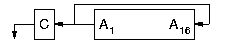
| ALR | SH | 0416 | Logical Left Rotate |
The A register is shifted left, end-around (n) positions. A1 is shifted out to A16 and the C bit. The C bit takes the state of the last bit shifted into A16. |
1+n/2 | 0.96+0.48n |
| ALS | SH | 0411 | Arithmetic Left Shift |
The A register is shifted left (n) positions. If shifting causes a change in the sign of A at any time during the instruction, the C bit is set. If the sign is not changed, the C bit is reset. After 16 or more shifts , the A register contains ZERO. |
1+n/2 | 0.96+0.48n |
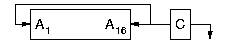
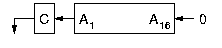
| ARR | SH | 0406 | Logical Right Rotate |
The A register is shifted right, end around (n) positions. Bits shifted out of A16 enter A1 and the C bit. The C bit takes the state of the last bit shifted out of A16 |
1+n/2 | 0.96+0.48n |
| ARS | SH | 0405 | Arithmetic Right Shift |
The A register is shifted right (n) positions. The sign bit (A1) does not change; it is shifted into vacated positions of the register. Bits shifted out of A16 enter the C bit. The C bit takes the state of the last bit shifted out of A16. If 15 or more shifts are specified, all the bits of the A register will be the same as the sign bit. |
1+n/2 | 0.96+0.48n |
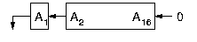
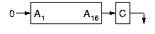
| LGL | SH | 0414 | Logical Left Shift |
The A register is shifted left (n) positions. ZEROs fill in the vacated bit positions. A1 is shifted to the C bit. Bits shifted out of C are discarded. After 16 or more shifts, The A register contains ZERO. The C bit takes the state of the last bits shifted out of A1. |
1+n/2 | 0.96+0.48n |
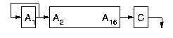
| LGR | SH | 0411 | Logical Right Shift |
The A register is shifted right (n) positions. A16 is shifted to the C bit. Bits shifted out of C are discarded. After 16 or more shifts, the A register conatins ZERO. The C bit takes the state of the last bit shifted out of A16. |
1+n/2 | 0.96+0.48n |
| LLL | SH | 0410 | Long Left Logical Shift |
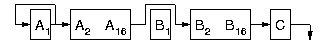
The A and B registers are treated as a single 32-bit register (A being the most significant) and shifted left n positions. ZEROs are shifted into vacated positions of B. bits are shifted from B1 to A16. Each bit shifted out of A1 enters the C bit. Bits shifted out of the C bit are discarded. If 32 or more shifts are specified, the A and B registers will contain ZERO. The C bit takes the state of the last bit shifted out of A1. |
1+n/2 | 0.96+0.48n |
| LLR | SH | 1412 | Long Left Rotate |
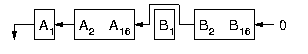
The A and B registers are treated as a single 32-bit register and are shifted left, end around, (n) positions. Bits shifted out of B1 enter A16; bits shifted out of A1 enter B16 and the C bit. Bits shifted out of the C bit are discarded. The C bit takes the state of the last bit shifted into B16 |
1+n/2 | 0.96+0.48n |
| LLS | SH | 0411 | Long Arithmetic Left Shift |
The A and B registers are treated as a single 31-bit register (B1 is not changed) and shifted left n positions. ZEROs are shifted into vacated positions through B16. Bits shifted out of B2 enter A16. If at any time during the instruction the sign of the A register (A1) is changedm the C bit is set. If at the end of the instruction the sign has not changed, the C bit is reset. If 31 or more shifts are specified, the A and B registers contain ZERO (except for B1, which is unchanged). |
1+n/2 | 0.96+0.48n |
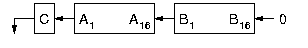
| LRL | SH | 0400 | Long Right Logical Shift |
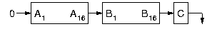
The A and B registers are treated as a single 32-bit register (A being the most significant) and shifted right n positions. Bits shifted out of A16 enter B1. Bits shifted out of B16 enter the C bit. Bits shifted out of the C bit are discarded. ZEROs are shifted into vacated positions through A1. The C bit takes the state of the last bit shifted out of B16. If 32 or more shifts are specified, the A and B registers will contain ZERO. |
1+n/2 | 0.96+0.48n |
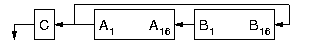
| LRR | SH | 0402 | Long Right Rotate |
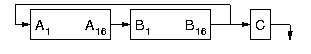
The A and B registers are treated as a single 32-bit register (A being the most significant) and shifted right, end-around (n) positions. Bits shifted out of A16 enter B1. Bits shifted out of B16 enter A1 and the C bit. Bits shifted out of C are discarded. The C bit takes the state of the last bit shifted into A1. |
1+n/2 | 0.96+0.48n |
| LRS | SH | 0411 | Long Arithmetic Right Shift |
The A and B registers are treated as a single 31-bit register (B1 is not changed) and shifted right (n) positions. The sign bit, A1, is not changed; it is propogated into vacated positions of the register. Bits shifted out of A16 enter B2. Bits shifted out of B16 enter the C bit. (Bits shifted out of the C bit are discarded.) After 30 or more shifts, both registers are filled with the sign of the A register, except for B1, which is unchanged. The C bit takes the state of the last bit shifted out of B16. |
1+n/2 | 0.96+0.48n |
| Mnemonic | Type | Op Code | Definition | Description | No. of Cycles | Time (µ sec) |
|---|---|---|---|---|---|---|
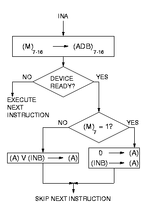
| INA | IO | 54 | Input to A |
|
2 | 1.92 |
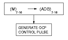
| OCP | IO | 14 | Output control pulse |
|
2 | 1.92 |
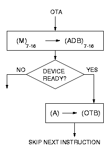
| OTA | IO | 74 | Output from A |
|
2 | 1.92 |
| SMK | IO | 74 | Set Mask (Special OTA) | (A) -> (OTB) Generate SMK pulse to transfer output bus to external device mask flip-flops. This instruction does not skip. |
2 | 1.92 |
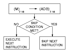
| SKS | IO | 34 | Skip if Ready Line Set |
|
2 | 1.92 |
| Mnemonic | Type | Op Code | Definition | Description | No. of Cycles | Time (µ sec) | ||||||
|---|---|---|---|---|---|---|---|---|---|---|---|---|
| CAS | MR | 11 | Compare |
Algebraically compare (A) and [EA]
|
3 | 2.88 | ||||||
| ENB | G | 000401 | Enable Program Interrupt | Set machine status to permit interrupt. The permit interrupt status will not tae effect until the instruction immediately following ENB is completed. (PI indicator lights.) | 1 | 0.96 | ||||||
| HLT | G | 000000 | Halt | Sets machine to halt mode. No further instructions or interrupts will be serviced until the console START button is pressed, at which time normal execution resumes. | ||||||||
| INH | G | 001001 | Inhibit Program Interrupt | Resets "permit interrupt status" to prohibit standard or priority interrupts. (PI indicator is extinguished.) | 1 | 0.96 | ||||||
| IRS | MR | 12 | Increment, replace and skip | [EA] + 1 -> [EA] If [EA] + 1 = 0, skip next instruction |
3 | 2.88 | ||||||
| JMP | MR | 01 | Unconditional Jump | [EA] -> (P) Next instruction to be executed is at location EA |
1 | 0.96 | ||||||
| JST | MR | 10 | Jump and store location | (P3-16) -> [EA3-16] [EA1,2] not changed EA3-16 + 1 -> (P3-16) |
3 | 2.88 | ||||||
| NOP | G | 101000 | No Operation | Performs no operation. Computer proceeds to next instruction. | 1 | 0.96 | ||||||
| RCB | G | 140200 | Reset C bit | 0 -> (C) | 1 | 0.96 | ||||||
| SCB | G | 140600 | Set C bit | 1 -> (C) | 1 | 0.96 | ||||||
| SKP | G | 100000 | Unconditional skip | Skip next instruction | 1 | 0.96 | ||||||
| SLN | G | 101100 | Skip if (A16) One | If (A16) = 1: skip next instruction | 1 | 0.96 | ||||||
| SLZ | G | 100100 | Skip if (A16) Zero | If (A16) = 0: skip next instruction | 1 | 0.96 | ||||||
| SMI | G | 101400 | Skip if A Minus | If (A1) = 1: skip next instruction | 1 | 0.96 | ||||||
| SNZ | G | 101040 | Skip if A Not Zero | If (A) != 0: skip next instruction | 1 | 0.96 | ||||||
| SPL | G | 100400 | Skip if A Plus | If (A1) = 0: skip next instruction | 1 | 0.96 | ||||||
| SR1 | G | 100020 | Skip if Sense Switch 1 is Reset | If Sense Switch 1 is OFF: skip next instruction | 1 | 0.96 | ||||||
| SR2 | G | 100010 | Skip if Sense Switch 2 is Reset | If Sense Switch 2 is OFF: skip next instruction | 1 | 0.96 | ||||||
| SR3 | G | 100004 | Skip if Sense Switch 3 is Reset | If Sense Switch 3 is OFF: skip next instruction | 1 | 0.96 | ||||||
| SR4 | G | 100002 | Skip if Sense Switch 4 is Reset | If Sense Switch 4 is OFF: skip next instruction | 1 | 0.96 | ||||||
| SRC | G | 100001 | Skip if C Reset | If (C) = 0: skip next instruction | 1 | 0.96 | ||||||
| SS1 | G | 101020 | Skip if Sense Switch 1 is Set | If Sense Switch 1 is ON: skip next instruction | 1 | 0.96 | ||||||
| SS2 | G | 101010 | Skip if Sense Switch 2 is Set | If Sense Switch 2 is ON: skip next instruction | 1 | 0.96 | ||||||
| SS3 | G | 101004 | Skip if Sense Switch 3 is Set | If Sense Switch 3 is ON: skip next instruction | 1 | 0.96 | ||||||
| SS4 | G | 101002 | Skip if Sense Switch 4 is Set | If Sense Switch 4 is ON: skip next instruction | 1 | 0.96 | ||||||
| SSC | G | 101001 | Skip if C Set | If (C) = 1: skip next instruction | 1 | 0.96 | ||||||
| SSR | G | 100036 | Skip if No Sense Switch Set | If no Sense Switches are ON: skip next instruction | 1 | 0.96 | ||||||
| SSS | G | 101036 | Skip if Any Sense Switch Set | If any Sense Switches are ON: skip next instruction | 1 | 0.96 | ||||||
| SZE | G | 100040 | Skip if A Zero | If (A) = 0: skip next instruction | 1 | 0.96 |
| Mnemonic | Type | Op Code | Definition | Description | No. of Cycles | Time (µ sec) |
|---|---|---|---|---|---|---|
| CAL | G | 141050 | Clear A, Left Half | 0 > (A1-8) (A9-16) are unchanged |
1 | 0.96 |
| CAR | G | 141044 | Clear A, Right Half | 0 > (A9-16) (A1-8) are unchanged |
1 | 0.96 |
| ICA | G | 141340 | Interchange Characters in A | (A1-8) <-> (A9-16) A1 is interchanged with A9, A2 with A10, etc. |
1 | 0.96 |
| ICL | G | 141140 | Interchange and Clear Left Half of A | (A1-8) -> (A9-16) 0 -> (A1-8) Bits 9-16 of A are replaced with bits 1-8; bits 1-8 are cleared. |
1 | 0.96 |
| ICR | G | 141240 | Interchange and Clear Right Half of A | (A9-16) -> (A1-8) 0 -> (A9-16) Bits 1-8 of A are replaced with bits 9-16; bits 9-16 are cleared. |
1 | 0.96 |